Weather Station
Posts in this series
- Introduction
- Sensor hardware prototype
- Powering the sensor
- Final sensor hardware
- Sensor software
- Receiver hardware
- Receiver software
- Final build & installation
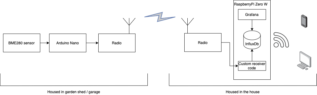
At the end of the last post we had the outline of a remote weather sensor transmitting data back to a base station for recording and visualisation.
We had a set of requirement that the sensor should be battery powered, with long life. The sensor module should be capable of recording the current temperature, humidity and pressure as a minimum. As I’m still new to the microcontrollers, it should be based on an Arduino due to the amount of support available on the internet.
In this post I’ll go over the prototyping a sensor, testing power sources, transmitter basics and things I’ve learnt along the way.
Initial design
My initial design was to use a Arduino Nano as the micro controller for the project, hooked up to a BME-280 sensor module and HC-12 as the transmitter.
I chose the Nano as it was:
- Cheap
- Easily available
- Can be programmed over USB
- Has a decent amount of I/O
- Used the same AVR chip as the Arduino Uno I’d used before.
- Low power (I’d assumed, more on this later)
Temperature, pressure and humidity sensor - BME 280
My initial experiment used a DHT-11 sensor, these are very cheap but suffer from poor accuracy (±2 degrees) and low resolution (1 degree).
The BME sensor range by Bosch, specifically the BME-280 seemed like a good fit for this project, low price & power requirements, easily available at a good price. Temperature accuracy seems to be only in the ±1 degree mark, but the resolution is higher than the DHT-11 at 0.01˚C. I bought mine for around £4 on amazon.
This sensor an I2C interface making it easy to read from the arduino.
The HC-12 transmitter
Next up was a means of transmitting the sensor values back to the Pi. I wanted to place the sensor on the shed at the bottom of my garden. This is around 7 meters from the house & not an area where I can get reliable Wifi coverage, taking Wifi or Bluetooth modules out of the equation.
Instead I started looking at 433MHz modules. There are plenty of cheap RF modules available, but I was concerned about the range and reliability transmitting data on these modules. I didn’t want to have to write tonnes of error correction code!
Looking for alternatives I chose to use the widely available HC-12. The HC-12 relatively cheap (~£6 per module) long range (up to 1KM) transmitter / receiver that works on the unlicenced 433MHz band. It provides a simple serial input and output, no software libraries are required. Unlike simpler cheap 433MHz transmitters each module can both send and receive, although it cannot both transmit and receive at the same time (known as simplex rather than duplex). While I was only intending each as either a transmitter or Receiver, being able to use one type of module seemed like a positive.
I went with this two pack.
Be careful of low quality clones, these may have limited range. This video from the Tech Bros shows how to identify clones and a potential simple fix.
Configuring the HC-12
The transmitter module has a number of settings from the wireless channel to transmit/recieve on, to the amount of power & the baud rate at which to transmit at.
We will need to configure the HC-12 modules transmission and recieve settings. The HC-12 stores its settings on a onboard memory, so this only needs to be done once. Both the sender and Receiver module need to be configured identically. To configure the module, the set pin is pulled HIGH and AT style commands are sent over the serial interface.
The HC-12 datasheet gives full details on the settings avaliable.
Serial Writer
To modify the settings I mofified a Arduino program from Tom Heylen that allows you to use the Arduino Serial Monitor to interact directly with the HC-12 in command mode.
//HC-12 AT Commander
//Modified from:
//Author Tom Heylen tomtomheylen.com
//The HC-12 commander mode runs at baud rate 9600


#include <SoftwareSerial.h>


#define HC_RX 2
#define HC_TX 3
#define HC_SET 4

SoftwareSerial radioSerial(HC_TX, HC_RX); // Arduino RX, TX

void setup() {
  Serial.begin(1200);
  Serial.println("Enter AT commands:");
  radioSerial.begin(1200);

  pinMode(HC_SET,OUTPUT);
  digitalWrite(HC_SET,LOW);
}

void loop(){
  if (radioSerial.available()){
    Serial.write(radioSerial.read());
  }
  if (Serial.available()){
    radioSerial.write(Serial.read());
  }
}
To use
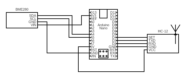
- Connect pin 2 on the arduino to the RX pin on the HC-12
- Connect pin 3 on the arduino to the TX pin on the HC-12
- Connect pin 4 on the arduino to the SET pin on the HC-12
- Connect the GND pin on the arduino to GND on the HC-12
- Connect PWR on the VCC to the arduino +5v pin
Upload the SerialWriter code the arduino and open the Serial Monitor (Tools -> Serial Monitor).
Enter the command to send to the HC-12 and click send, eg, entering AT+V will return the firmware of the HC-12.
If you see garbled text, you may need to change the baud rate of the terminal down to 1200bps.
www.hc01.com HC-12 v2.6
Transmission range
In the UK, the 433MHz unlicenced band is resticted to 10mW of power. The HC-12 can go up to 100mW. From the datasheet, the HC-12 has 8 power levels, from 0.8mW up to 100mW power. The default is the full 100mW power setting. To keep within 10mW I can use power levels 1 - 4.
In addition the module has 4 transmission modes that affect its range and the over the air bandwidth. These are FU1 - FU4, with FU3 being the default.
- FU1 - Short range - 100m, moderate power savings (3.6mA at idle), max bandwith 236kbps
- FU2 - Extreme power saving, 100m range, 80uA at idle, max bandwidth 4800bps
- FU3 - The default, upto 1000m range, 16mA at idle, max bandwidth 236kbps
- FU4 - Long range mode, 16mA idle, but low bandwidth 1200bps only & fixed packet size.
In general, the lower the transmitting bandwidth, the greater the range. The greater the power setting, the greater the range.
Range testing
For my use case, with the transmitter running on battery power, I want to transmit power as low as possible. As communication is one way, idle power is not a concern as I’ll power down the transmitter when not required. The distance between the transmitter and sensor is only 20 metres. However the are a number of walls the signal needs to go through which caused transmission errors and dropouts.
Putting the HC-12 to sleep mode uses just 22uA (AT+SLEEP).
To test the best settings for the distance required, I created a Python script that ran on the Pi, and broadcasts on a 3 second frequency.
#!/usr/bin/env python3

import serial
import time

ser = serial.Serial(

	port='/dev/ttyS0',
	baudrate=1200,
        parity=serial.PARITY_NONE,
	stopbits=serial.STOPBITS_ONE,
	bytesize=serial.EIGHTBITS,
	timeout=30
    )


while 1:
    ser.write(b'H')
    ser.close()
    time.sleep(3)
    print("ping \n")
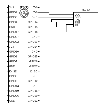
The HC-12 was wired up to GPIO pins 14 & 15 which also act at the Transmit and Recieve serial pins.
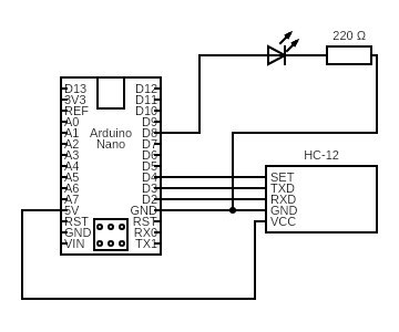
I hooked up an LED to the arduino on pin 8, with a 220 ohm resistor inline and coded the arduino to flash the LED for 1 second when it recieved a valid message. This allowed me to place the Pi in its final location and by powering the arduino from a battery pack walk around to determine the range.
#include <SoftwareSerial.h>

#define HC_RX 2
#define HC_TX 3
#define HC_SET 4
#define LED 8

SoftwareSerial radioSerial(HC_TX, HC_RX); // Arduino RX, TX

void setup() {
  pinMode(LED, OUTPUT);
  Serial.begin(9600);
  Serial.println("Ready to receive");
  radioSerial.begin(1200);
  digitalWrite(LED, HIGH);   // turn the LED on (HIGH is the voltage level)
  delay(500);                       // wait for a second
  digitalWrite(LED, LOW);    // turn the LED off by making the voltage LOW
}

void loop(){
  if (radioSerial.available()){
    Serial.println("Available");

    char msg = radioSerial.read();
    Serial.println(msg);
    if(msg == 'H'){
      digitalWrite(LED, HIGH);   // turn the LED on (HIGH is the voltage level)
      delay(1000);                       // wait for a second
      digitalWrite(LED, LOW);    // turn the LED off by making the voltage LOW
    }
  }
}
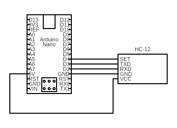
The arduino was wired up with:
- D2 to the HC-12’s Rx
- D3 to the HC-12’s Tx
- D4 to the HC-12’s Set
- The LED off D8
I’m only going to be sending a few bytes of data for each reading, so the speed of the transmission isn’t too important. However as I won’t be acknowledging any measurements or have any way to ask the sensor to repeat a reading having a reliable connection is important. For this reason I went with the lowest baud rate of 1200bps. Why aren’t I acknoledging the message? See a bit further down.
Experimentation has shown that the following worked for my requirements:
- FU3 (simplest transmission mode)
- 1200bps (Lower baud rate for maximum range)
- Channel 1 was fine
- Power level 4 (6.3mW)
Running AT+RX on the serial console returns:
OK+B1200
OK+RC001
OK+RP:+08dBm
OK+FU3
Antennas
The pack of modules I bought came with simple spring antennas that you solder to the ANT connection on the board. These were sufficient short range testing indoors and worked fine in open spaces. The range testing above was done with the spring antennas. For longer distances or with obstacles in the way the board has a I-PEX / U.FL connector that allows external antennas to be connected.
Alternatively you can try building your own from just a piece for wire.
To get the most reliable signal (I would get the odd partial / corrupt message) I went with a pair of external antennas.
Acknowledge the message
I mentioned that I wanted as reliable as possible connection between the sender and receiver earlier, so why don’t I get the Receiver to acknowledge the weather reading message & the sender to retry? You could even increase the transmission power if the message is not received before trying again & skip the range experiments above…
There’s two reasons why I didn’t go down this rabbit hole:
- Simplicity
-
Power usage
-
Simplicity This would make both the sending code and the receiving code much more complicated to understand and debug when something went wrong. There’s additional edge cases to manage there. If the receiver is switched off, how many times do you retry before give up? What would happen if the receiver does receive the message, but the sender doesn’t receive the acknowledgement back? This would be a case of the two generals problem explained well by Tom Scott.
- Power usage After sending a message the sensor would need keep the powered up whilst waiting for a response rather than quickly powering down. Keeping the arduino and the HC-12 powered up for a few seconds while waiting to receive a ack & potentially retrying will use much more power than quickly powering down the system.
Weather data won’t be changing quickly, missing a single reading or two is unlikely to make much of a difference. Instead of adding the software complexity and additional power usage of acknowledging a message we can simply increase the measuring rate up to a frequency where a missed message or two doesn’t cause problems.
Conclusion
We’ve picked the hardware for the sensor, created a prototype and done some testing of the configuration of the transmitter.
Next time: How to power the sensor, minimising power usage and a change in plans.