Weather Station
Posts in this series
- Introduction
- Sensor hardware prototype
- Powering the sensor
- Final sensor hardware
- Sensor software
- Receiver hardware
- Receiver software
- Final build & installation
Final design
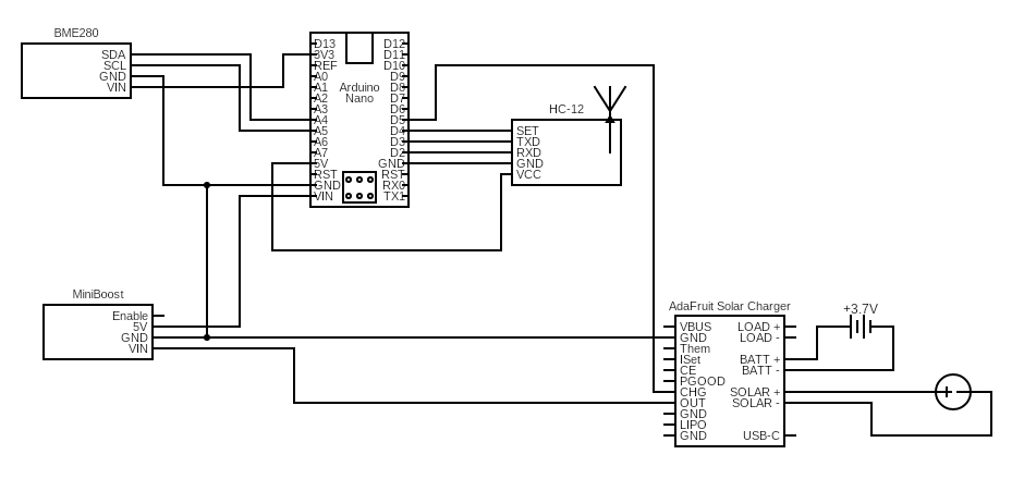
After the power experiments we have a final circuit design for our solar powered sensor & a breadboard prototype.
Now its time to create something a bit more rugged that can survive outside.
Circuit board
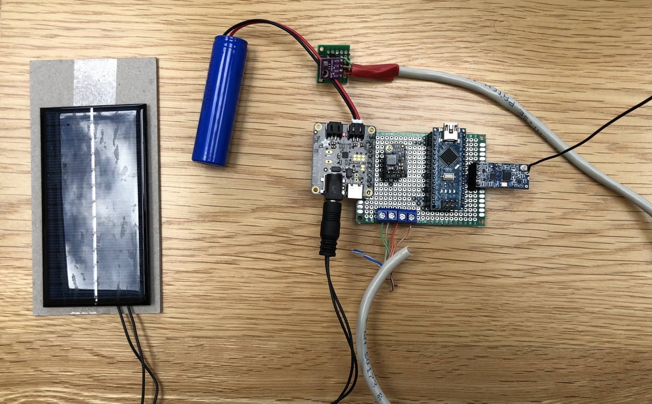
As this is a one off, I went with a simple perfboard solution for the circuit board. I decided to socket all the components with pin header connectors. This would make it easier to replace any components in the future & as heat from a soldering iron can damage components, it would make it a bit safer.
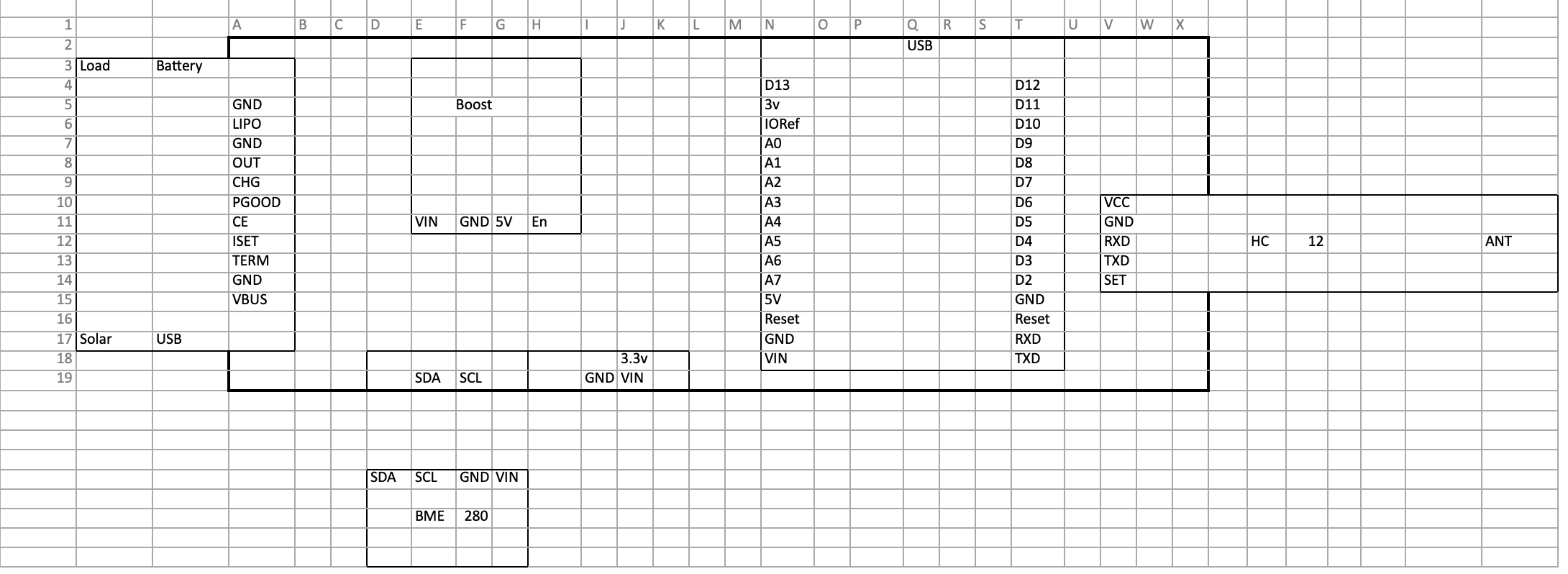
To layout the board, I measured the size of each component in terms of pin holes in the perfboard, then used (of all things) Excel to layout the components on the board.
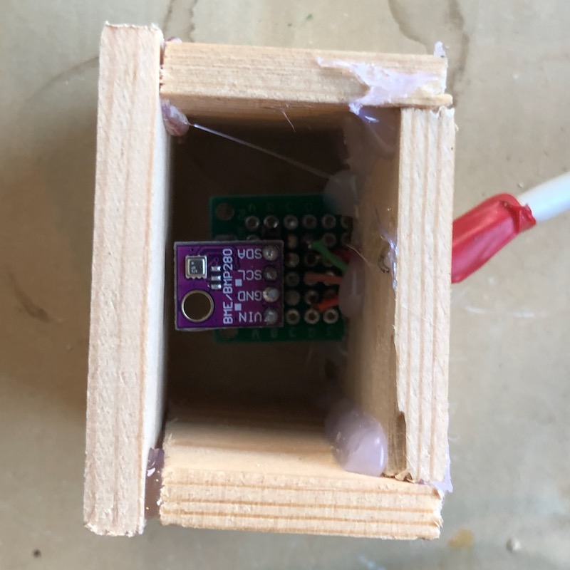
The BME-280 sensor would be on a seperate board, to allow it to be placed outside in its own housing. I repurposed an old Ethernet cable to connect the two boards together. This gave plenty of wires for connecting the two together, but wasn’t the best choice. Each individual wire was made up of multiple strands rather than a single core, making it difficult to achieve a good connection. It works well enough, but I wouldn’t recommend reusing an ethernet cable this way.
Casing
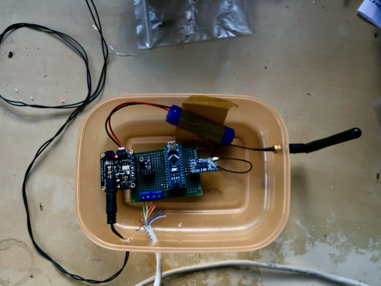
The receiver will be housed inside a garden shed, to give it an element of weatherproofing I repurposed a tupperware box to mount the components in. Its not at all waterproof, but should provide a bit of protection.
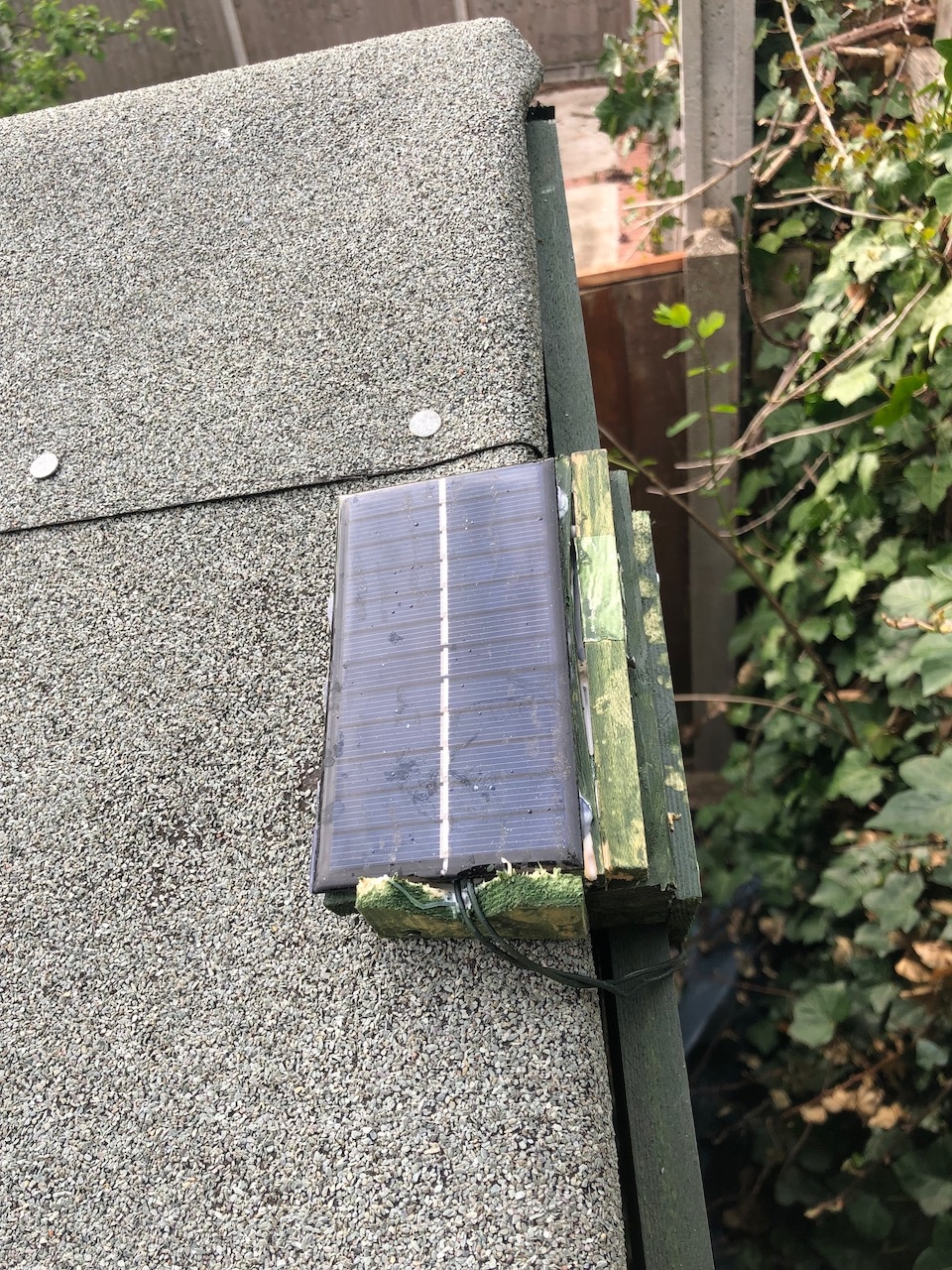
The sensor itself will be housed outside, to house the sensor I built a small wood box & painted it to match the exterior of the shed. I’m by no means an expert at woodworking, but its held together so far.
Finally I created a platform to mount the solar panel to & angle it towards the sun.
With that done, the sensor is complete, on to the Receiver.