Weather Station
Posts in this series
- Introduction
- Sensor hardware prototype
- Powering the sensor
- Final sensor hardware
- Sensor software
- Receiver hardware
- Receiver software
- Final build & installation
Last time we selected a sensor and transmitter module and ran some range tests. This time we’ll be looking at how to power the sensor on battery power. One of the requirements back at the start was for the sensor module to run outside, on batteries for a significant amount of time. This is for my own benefit, realistically if I’m having to change or charge batteries every few weeks its not going to get done (especially in the winter!).
Power testing
I purchased the arduino nano clone before doing much research into how to power these from a battery, I had just assumed they would be pretty low power & I could easily power them from a large USB battery bank I had spare. It turns out this was a number of false assumptions.
USB power bank
My first test involved writing the simplest unoptimised program on the arduino to take sensor readings from the BME-280 sensor and transmit these values over the HC-12.
I set it up in the office and kept an eye on the power bank levels, after around 5 days the battery was dead. This gives a rough current draw of ~46mAh. Not high for a device plugged into the wall, but it quickly drains a battery. Later testing of the nano hooked up to directly to a battery showed a much lower current draw when active, closer to 20mAh, so I suspect the are some inefficiencies in the power regulator when in powering a nano from the USB & my cheap battery bank is probably a bit lower than the 5000mAh it claims to be.
Software optimisations
Being a software developer, I first looked at what software modifcations could be made. Running the arduino at full power continuously is a great way to run the batteries down quickly. As we’re taking readings for a few seconds per hour, putting all the components in to a low power state would be a great way to increase battery life.
Powering down the BME-280
When running the BME-280 draws a few milliamps. Its a small power draw, but adds up over time. We can reduce this by setting the sensor to sleep by default, while sleeping the power usage is in the micro-amps range.
bmeSensor.setMode(MODE_SLEEP);
When a reading is required, the sensor is woken up briefly & read, before being put back to sleep.
    void sensorUpdate(){
        bmeSensor.setMode(MODE_FORCED); //Wake up sensor and take reading
        while(bmeSensor.isMeasuring() == false) ; //Wait for sensor to start measurment
        while(bmeSensor.isMeasuring() == true) ; //Wait until the sensor completes the reading
        bmeSensor.setMode(MODE_SLEEP);
    }
Sleeping the HC-12
The HC-12 uses around 16ma while idle waiting to receive a message. Putting the module to sleep brings the power down into micro-amp range. This is done by putting the module in to command mode (Pulling SET to high) and sending the command AT+SLEEP, the module powers down when exiting command mode (pulling setting the SET pin to low).
/* Sends AT command to HC-12 & checks response to determine if awake
 *
 */
void hc12WakeUp(){
  String wakeResponse = sendHC12Command("AT");
  if(!wakeResponse.equals("OK")){
    Serial.println("HC-12 error while trying to wake up");
    Serial.print(wakeResponse);
    errorFlash(5);
  }
}

/**
 * Sends a HC-12 command and returns the response as a string
 * Max response buffer size: RESPONSE_BUFFER bytes
 */
String sendHC12Command(String command){

  //Go to command mode
  digitalWrite(HC_SET,LOW);
  delay(100); //Specs ask for at least 40ms delay before programming
  radioSerial.print(command);
  delay(100); //Spec asks for at least 80ms delay before

  String response = "";

  while (radioSerial.available())
  {
    char character = radioSerial.read(); // Receive a single character from the software serial port
    response.concat(character); // Add the received character to the receive buffer
  }
  response.trim(); //Strip whitespace at end


  Serial.print("HC-12 command: ");
  Serial.print(command);
  Serial.print(" response: ");
  Serial.println(response);


  //Exit command mode
  digitalWrite(HC_SET,HIGH);
  delay(100); //Spec asks for at least 80ms delay before transmitting serial data
  return response;
}
Sleeping the arduino
I’m using the LowPower library to simplify power management. This library allows parts of the arduino to be powered down and gives a simple command to sleep the system for up to 8 seconds.
We won’t be using the analog to digital converter at all, so this is powered down in the setup function
    void setup(){
        // disable ADC
        ADCSRA = 0;
    }
Between weather reading we can now power down the system fully. This command goes into the lowest power state for 8 seconds, to sleep for longer we simply call this multiple times in a loop. Eg setting define SLEEP_PERIOD 10 will sleep the arduino for 10 x 8 = 80 seconds.
    for(int i =0; i < SLEEP_PERIOD; i++){
        LowPower.powerDown(SLEEP_8S, ADC_OFF, BOD_OFF);
    }
Reducing the clockspeed
The Nano runs at a 16MHz clock frequency by default. While incredibly slow compared to a modern computer, this is more than enough for a simple sensor & could be be reduced significantly. The clock speed can be divided down to 8/4/2MHz with a reduction in power consumption directly through software.
The following code will run the arduino at 8MHz.
    void setup() {
        CLKPR = 0x80; // (1000 0000) enable change in clock frequency
        CLKPR = 0x01; // (0000 0001) use clock division factor 2 to reduce the frequency from 16 MHz to 8 MHz
    }
However, running my Arduino at 8MHz produced garbled messages being sent by the HC-12. I suspected this was due to data being sent over the serial port to the HC-12 at half the rate it expected, so I tried doubling the baud rate, but this didn’t resolve the problem.
Halving the clock rate means that it would take twice as long to run the measurement code, this could offset or negate any potential power savings running at a lower clock rate. Sometimes its best to finish a task quicker and sleep the arduino sooner.
The main benefit of running at a reduced clock rate is that you can run the arduino at a lower input voltage. As we’ll see below this isn’t possible for this case. With the potential power savings being low, I quickly gave up on trying to get my code working at 8MHz.
Lowering the input voltage
For some cases lowering the input voltage down to 3.3v, with the clockspeed reduced gives significant power reductions. I couldn’t go with this option, as I’ll need a 5v power supply for the HC-12 & didn’t want the complexity of managing two supply voltages.
Results
After these software mods I charged up the same battery bank & set the sensor up to start measuring and transmitting again. The run time increased, by about a day… This wasn’t what I was expecting.
Trying a different battery pack, to see if that made a difference I found out that I found out that if the arduino went into a deep enough sleep, the battery bank would switch off.
Hmmm. This USB battery pack idea was starting to cause more problems than it was worth. It was time to actually measure the power draw & take some measurements.
Power consumption testing
Having minimised power usage as much as possible through software I hooked up my multimeter to measure the power consumption of my Nano clone running weather readings.
The recommended input voltage for Vin pin is 7-12V, so I used a 9V battery to record the idle, sleeping and transmitting power.
| Mode | Power Usage |
|---|---|
| Idle | 18.5ma |
| Sleeping | 7ma |
| Transmitting | 40ma |
With these results the 5000mAh USB power supply should easily supply 30 days when idle, or over 10 days running with no optimisation. Clearly the USB power converter isn’t the most effective way to power this arduino.
Power options
With the original plan out of the window, lets look at alternative methods for power this sensor, with the following in mind:
- I need 5v for the HC-12, I can’t power the Nano from 3.3v only
- The batteries must last at least a month, ideally more than 3 months between changes
- No specialty/new chargers. I can charge with USB, AA battery chargers or even 12v Car batteries without buyingn new equipment.
A 7ma current draw whilst sleeping is pretty high, ideally the draw should 100 times lower for a simple sensor. Lets do a bit of maths to see how long we could run the weather station on normal AA batteries.
Using simple NiMh rechargable batteries we can either use 6 or 8 in series to get us to the required voltage range. Normal alkaline batteries at 1.5v would still be in spec for the Arduino.
The table below give some estimated run times based on the sleeping current draw. Actual times would be less.
| Number of batteries | Total Voltage @1.2v cell | Total Voltage @1.5/cell | Total mAh | Watt hrs | Run time in days | Cost |
|---|---|---|---|---|---|---|
| 6 - 2000mAh | 7.2 | 9 | 2000 | 14.4 | 12d | £11.5 |
| 8 - 2000mAh | 9.6 | 12 | 2000 | 19.2 | 12d | £11.5 |
| 6 - 2600mAh | 7.2 | 9 | 2600 | 18.7 | 15.5d | £12 |
| 8 - 2600mAh | 9.6 | 12 | 2600 | 25 | 15.5d | £12 |
| 8 - 800mAh | 9.6 | 12 | 800 | 7.7 | 5d | £7 |
| 12 - 6x2 in parallel | 7.2 | 9 | 5200 | 37.4 | 31d | £18 +6 |
| Lead acid 7ah | 12 | 7000 | 84 | 41.6d* | £16 |
* Lead acid batteries deteriate quickly if discharged below 50%, so the real capacity is 20 days.
Based on a few different capacities and configurations the best we can do is a month, using 12 AA batteries. That’s going to be a pain to manage & keep charged.
Hardware modifications
Optimising the software to use the power saving features of the hardware has got us down from a power draw of 18.5ma down to 7ma, better, but still pretty high for a continuous drain on battery power. It was time to look at hardware options.
Removing the power LED
Arduinos have a LED to indicate when the device is powered up, which can’t be disabled in software. I cracked out the soldering iron and carefully heated up the small surface mounted resistor in front of the LED & gently slid it off its pads. Running the power draw tests again showed reduction in power draw of 2ma, giving a 5ma draw on idle, definetly worth doing.
Others have gone to more extreme lengths to reduce the power draw on their projects, but for the Nano clone I have this seemed to be about as its worth doing.
Unlike the Arduino Pro, the Nano has a built in USB to serial interface chip to allow it to be easily programmed, which draws a few milliamps. This chip can be removed, but then I’d have no way to reprogram the arduino, this was not a step I’d want to take.
Results
The power draw has been reduced, but it’s looking like the sensor using AA batteries is out of the window.
Others had made this setup work, but it turns out that a arduino nano isn’t optimised for battery power operation. Reading around the subject, a couple of options came up:
- Use an external circuit to trigger powering up the arduino to take a measurement. The arduino takes and transmits a measurement the fully powers off.
- Rather than use a full arduino development board with its extra power losses, use a raw Atmega328 microcontroller & add the minimal supporting hardware.
In the end I decide to go a third way, which I hoped would mean I never had to charge a battery.
Going solar
Rather than ditch the Arduino Nano & have to start again with the hardware, I decided to look into solar as a power source. With a battery being topped up each day by a solar cell I wouldn’t have to worry about power draw as much & more importantly I’d never have to change a battery. For this simple usecase its probably overkill, but it also gave me the chance to learn a little about solar power.
This video give a good breakdown of what to think about when powering devices from solar. At a 5ma power draw at idle, I need 120mah to power the sensor for the day, additing in 20% for charging efficiency means I need 144mah per day for the sensor. A 1 watt panel would supply this in a single hour, so even in the darkest days of winter I’d expect the battery to be topped back up.
To effectively charge a battery from solar a special charger board is required that can handle the changing input current as the sunlight varies. I went with this charger from Adafruit. When the sun is out it will power the board and charge a LiPo battery. At night it will power the board from the battery. It requires input from a 6V panel and as plus has a USB C port that can also be used to charge the battery. It outputs a steady 4.4v, too low for the arduino, so I added this boost converter to increase the voltage to 5v.
Lithium batteries can be dangerous so rather than going for a cheap battery from Amazon/Ebay I went with this 2200mah battery from Pimoroni. It has protection circutry to stop it being over charged, or over discharged and short circuit protection, something you don’t get using a raw 18650 cell common in laptops and electric cars. This battery is pretty overkill for this use, 2200mah should power the sensor for a couple of weeks without any input from the solar panel. A smaller capacity LiPo would be an option, but the cost difference is minimal for the capacity & with the pouch style LiPo you need to be careful not to puncture the pouch, otherwise fire. The hard shell of the cell style battery appealed for this reason!
For the solar panel I when with this cheap 6V 1 watt panel off ebay.
I hooked these up on a breadboard and over the next few days verified the charging / discharging worked correctly.
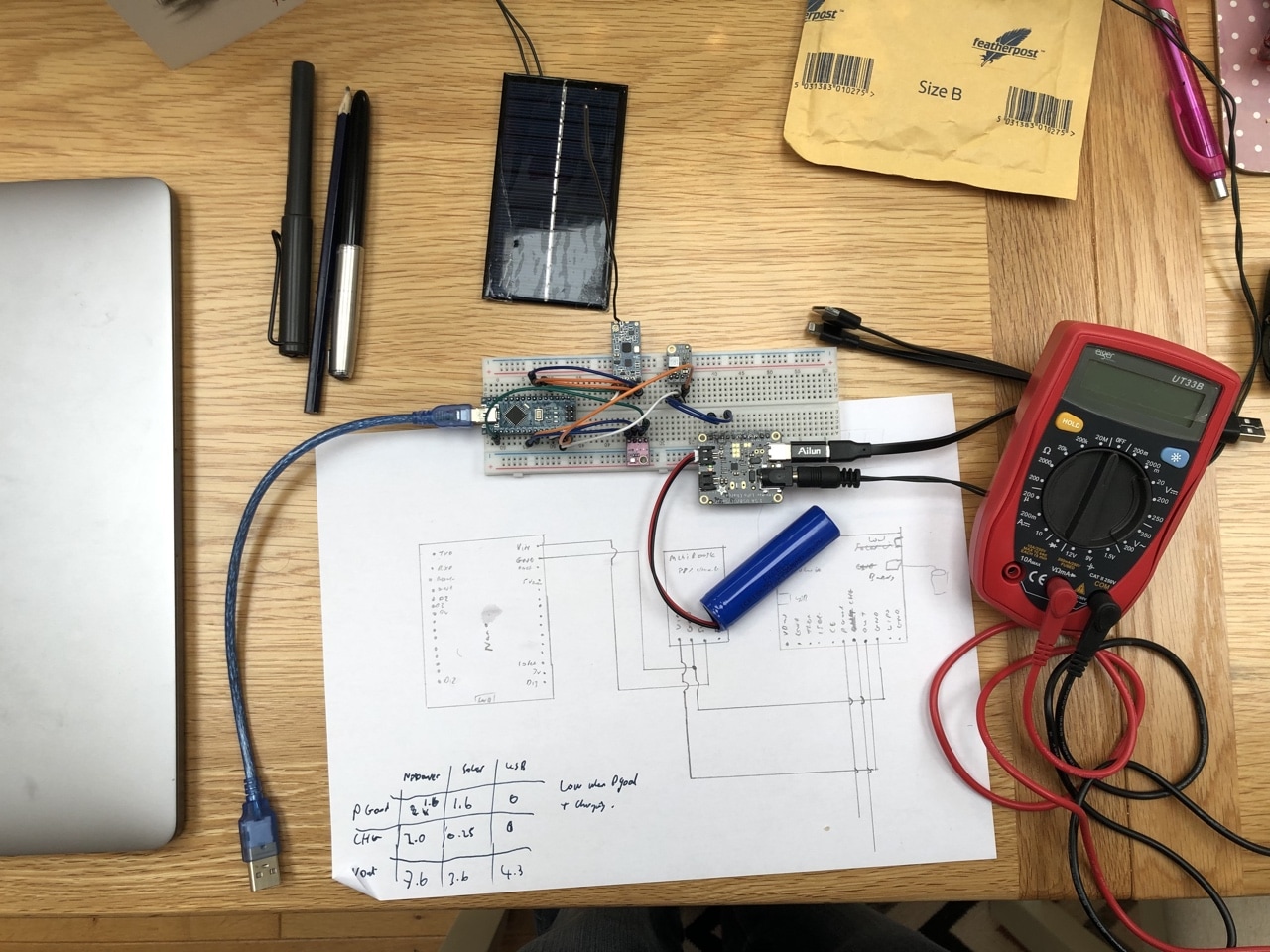
I added a wire from the Charge pin on the LiPo charger board to the arduino, this way I could report if the battery was being charged or discharged.
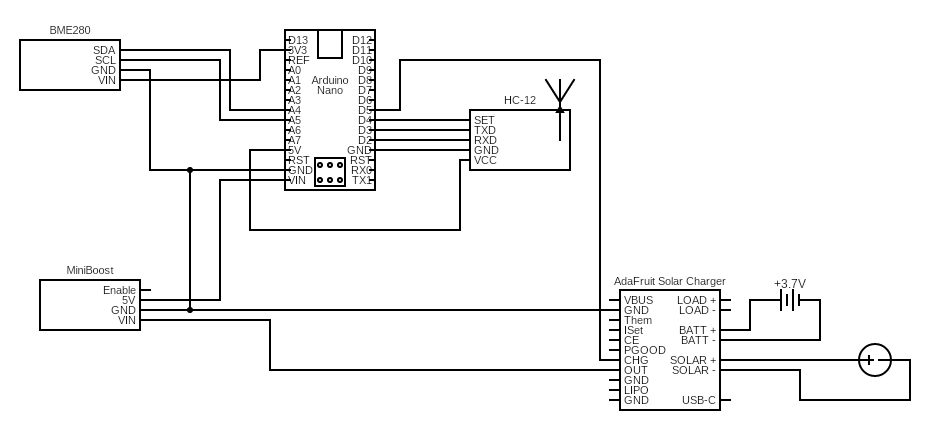
This give me this final circuit design for the sensor.
Conclusion
After a lot of experimentation we have a final choice of power for the sensor & a functional design on the breadboard. In the next section we’ll make a finish off with a case and proper circuit board the sensor.